Language:


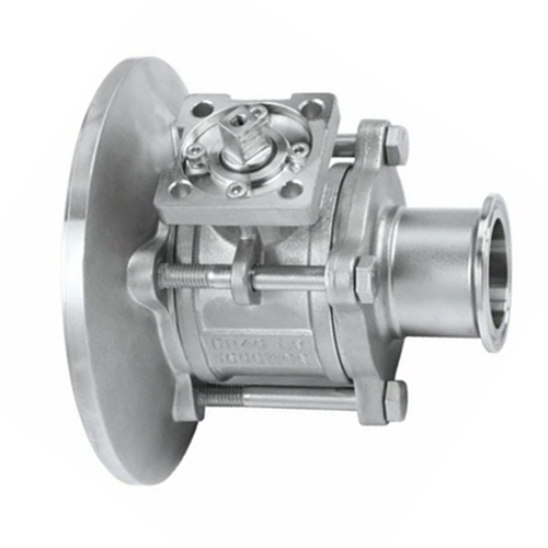
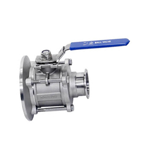
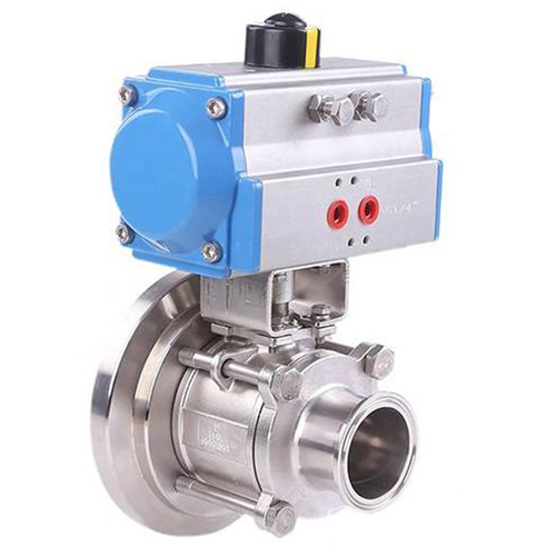
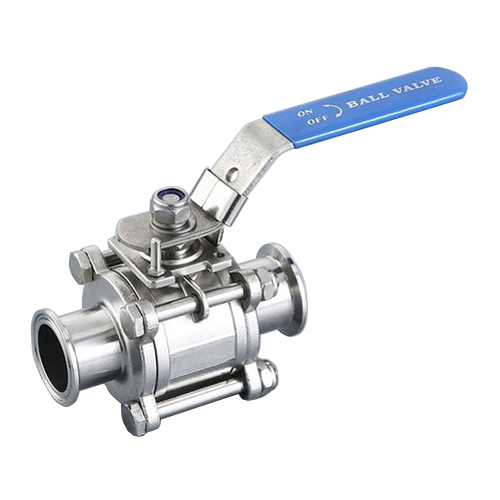
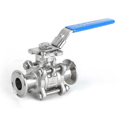
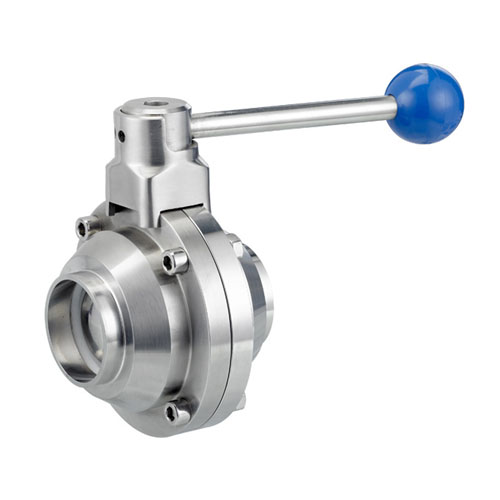
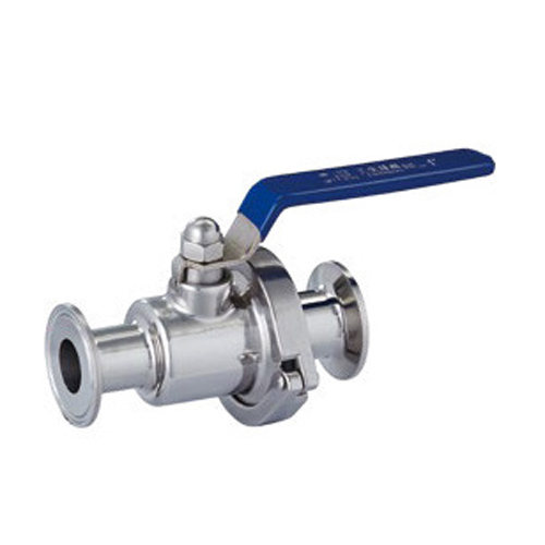
The tank bottom ball valve is used for pressure vessels and storage tanks of draining and discharging with the fully inclusive designed ball seat and compensation automatic type sealing . So it has advantage of high pressure, high temperature resistance, small torque, long life and other characteristics to meet CIP and SIP cleaning and sterilization. It is very suitable for the application in high cleanliness requirements in process systems such as pharmaceutical, food and beverage, dairy products, chemical industry etc..
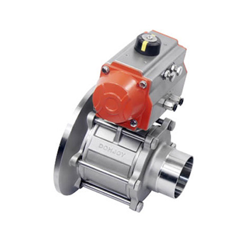
Pneumatic tank bottom ball valve can configure a variety of different actuators, electric, pneumatic and manual are interchangeable.
Size: DN25 ~ DN100, 1' ~ 4'
Pressure: 0 ~ 10bar
Material: ASTM 304 / 316L
Sealing material: PTFE, according to FDA
Working temperature: -30℃ ~ +130℃
Operating torque is small
Excretable
No matter what the flow fluid is, the handle can be mounted on the side of the valve body
No matter what kind of connection is, the valve can be replaced, without change the length of valve
Connection: Thread, Flange, Welding, Clamp, etc.
Operation Standard: DIN, SMS, RJT, 3A, ISO, IDF, BPE
Operation: Manually handle, electric pneumatic, stainless steel pneumatic, horizontal vertical pneumatic
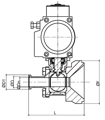
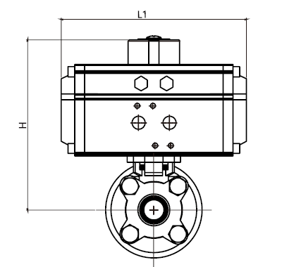
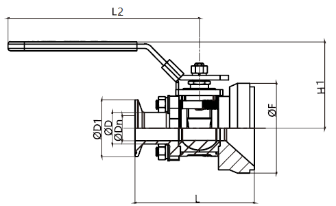
DIN Standard Weld / Clamp
|
Size |
Dn |
D |
K*K |
D1 |
L |
L1 |
L2 |
H1 |
H |
F |
|
DN25 |
25 |
28 |
11*11 |
50.5 |
106 |
155 |
170 |
78 |
114.5 |
120 |
|
DN40 |
37 |
40 |
14*14 |
50.5 |
125 |
168 |
173 |
98 |
177.5 |
120 |
|
DN50 |
49 |
52 |
14*14 |
64 |
140 |
219 |
173 |
107 |
202 |
150 |
|
DN65 |
66 |
70 |
14*14 |
91 |
155 |
249 |
223 |
151 |
230 |
180 |
|
DN80 |
81 |
85 |
17*17 |
106 |
176 |
274 |
335 |
160 |
258 |
212 |
|
DN100 |
100 |
104 |
17*17 |
119 |
210 |
315 |
335 |
169 |
292.5 |
248 |
3A Standard Weld / Clamp
|
Size |
Dn |
D |
K*K |
D1 |
L |
L1 |
L2 |
H1 |
H |
F |
|
1' |
22.1 |
25.4 |
11*11 |
50.5 |
106 |
155 |
170 |
78 |
114.5 |
120 |
|
1 1/2' |
34.8 |
38.1 |
14*14 |
50.5 |
125 |
168 |
173 |
98 |
177.5 |
120 |
|
2' |
47.5 |
50.8 |
14*14 |
64 |
140 |
219 |
173 |
107 |
202 |
150 |
|
2 1/2' |
60.2 |
63.5 |
14*14 |
77.5 |
155 |
249 |
223 |
130 |
230 |
180 |
|
3' |
72.9 |
76.2 |
17*17 |
91 |
176 |
274 |
335 |
153 |
258 |
212 |
|
4' |
97.4 |
101.6 |
17*17 |
119 |
210 |
315 |
335 |
169 |
292.5 |
248 |
Contact: Mask
Phone: +86 15801773163
Tel: +86 21-66168818
Email: sales@f-fluid.com
Add: Xuhui District, Shanghai, China